Masz to wszystko w serwisówce, ale mam to aktualnie pod ręką, także się zlituje

Błędy ECU w nissanach
For 4-cylinder:
1. Turn the ignition switch on, but do not start the engine. All of the lights in the dash should be on.
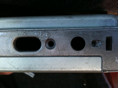
2. Turn the 'diagnostic mode selector' screw on the ECU fully clockwise. The check engine light will go out. Wait 5 seconds, then turn the screw fully counter clockwise.
3. The check engine light will then begin to flash the trouble code. (number of long flashes is the 1st digit, number of short flashes is the 2nd digit)
4. To clear all stored codes and turn the check engine light off, turn the screw fully clockwise while it is in diagnostic mode. Wait 5 seconds, then turn the screw fully counter clockwise.
5. To keep the codes stored, simply turn the key off as the check engine
light is flashing and the ECU will keep all stored codes and the check engine light will remain on.
For V6:
1. Turn the ignition switch on, but do not start the engine. All of the lights in the dash should be on.
2. For VG30i: There is a little plastic tab you pull off of the side of the ECU(facing the door). A small toggle switch is behind it with 2 positions, "ON" and "DIAGNOSTICS". Using a small screwdriver or tool, move it to the diagnostics position. The red and green LED's on top of the ECU will blink simultaneously. One time, pause, then 2 times, three times, pause...so on for each mode, 1 through 5. Mode 3 is the most commonly used mode and will yield the ECU trouble codes you need to figure out what's going on with your engine.
For VG30E with slotted switch: Turn the 'diagnostic mode selector' screw on the ECU fully clockwise. The check engine light will go out. Wait 5 seconds, then turn the screw fully counter clockwise.
3. After it blinks both LED's 3 times move the toggle switch back to the on position. After about five seconds it will start to output out the diagnostic codes as with the 4-cylinder ECU. Note each code as it is displayed, the red LED flashing once for 10's, and the green LED flashing once for 1's. Meaning: One red flash and two green flashes means code 12.
4. To clear the ECU of any trouble codes, move the switch to the "DIAGNOSTICS" position then back to the "ON" position and turn off the key.
1986.5-1995 Nissan ECU Flash Codes(all engines)
11 Crank Angle Sensor/Camshaft Position Sensor.
12 Air Flow Meter/Mass Air Flow Sensor.
13 Engine Coolant Temperature Sensor.
14 Vehicle Speed Sensor.
21 Ignition Signal.
22 Fuel Pump.
23 Idle Switch.
24 Throttle Valve Switch.
25 Idle Speed Control Valve.
28 Cooling Fan Circuit.
31 ECM.
32 EGR Function.
33 Heated Oxygen Sensor.
34 Knock Sensor.
35 Exhaust Gas Temperature Sensor.
36 EGR Control-Back Pressure Transducer.
37 Knock Sensor.
38 Right hand bank Closed Loop (B2).
41 Intake Air Temperature Sensor.
42 Fuel Temperature Sensor.
43 Throttle Position Sensor.
44 ECCS Normal Operation.
45 Injector Leak.
47 Crankshaft Position Sensor.
51 Injector Circuit.
53 Oxygen Sensor.
54 A/T Control.
55 No Malfunction.
63 No. 6 Cylinder Misfire.
64 No. 5 Cylinder Misfire.
65 No. 4 Cylinder Misfire.
66 No. 3 Cylinder Misfire.
67 No. 2 Cylinder Misfire.
68 No. 1 Cylinder Misfire.
71 Random Misfire.
72 TWC Function right hand bank.
73 TWC Function right hand bank.
76 Fuel Injection System Function right hand bank.
77 Rear Heated Oxygen Sensor Circuit.
82 Crankshaft Position Sensor.
84 A/T Diagnosis Communication Line.
85 VTC Solenoid Valve Circuit.
86 Fuel Injection System Function right hand bank.
87 Canister Control Solenoid Valve Circuit.
91 Front Heated Oxygen Sensor Heater Circuit right hand bank.
94 TCC Solenoid Valve.
95 Crankshaft Position Sensor.
98 Engine Coolant Temperature Sensor.
101 Front Heated Oxygen Sensor Heater Circuit right hand bank.
103 Park/Neutral Position Switch Circuit.
105 EGR and EGR Canister Control Solenoid Valve Circuit.
108 Canister Purge Control Valve Circuit
ECU Diagnostic Mode Procedures
Mode I - Exhaust Oxygen Sensor Monitor
-----------------------------------------------------------------------
Use Mode I to determine if the Oxygen Sensor is functioning properly.
Warm the engine to normal temperature.
Run the engine above 2000 RPM under no load while looking at the ECU.
Make sure the GREEN LED goes on and off more than five times during ten seconds at 2000 RPM.
If the number of flashes are not more than five, replace the oxygen sensor. If the LED does not flash, check the sensor's circuit.
Mode II - Mixture Ratio Control Monitor
-----------------------------------------------------------------------
Use Mode II to determine if the air/fuel mixture is cycling correctly.
Warm the engine to normal operating temperature.
Turn the dial on the ECU fully clockwise (or if you have a switch, turn it on).
After the LED flashes twice, turn the dial fully counter clockwise (or turn the switch off).
Run the engine above 2000 RPM under no load while looking at the ECU.
If the RED LED blinks simultaneously with the GREEN LED, the air/fuel mixture is cycling properly.
If the RED LED stays off, the mixture is more than 5% rich.
If the RED LED stays on, the mixture is more than 5% lean.
If the RED LED stays on or off above 2000 RPM, complete the diagnostics before beginning repairs.
Mode III - Stored Fault Code Reporting
-----------------------------------------------------------------------
Use Mode III to retrive all stored trouble codes in memory.
Use the above posted procedures.
Mode IV - Switch Operation Monitor
-----------------------------------------------------------------------
Use Mode IV to determine if the Throttle Position Sensor (TPS), Starter circuit and/or Vehicle Speed Sensor (VSS) are in proper working order.
Turn the ignition switch on, but do not start the engine.
Turn the dial on the ECU fully clockwise. After the LED flashes 4 times, turn the dial fully counter clockwise.
Make sure the RED LED is turned off.
Make sure the RED LED turns on when depressing the gas pedal. If not, check or replace the Throttle Position Sensor.
Make sure the RED LED turns on when turning the ignition key the START position. If not, check or replace the starter.
Drive the vehicle with the ECU unbolted and within view. Make sure the GREEN LED turns on when speed is 12 MPH or more. If not, check or replace the Vehicle Speed Sensor.
Mode V - Real Time Diagnostic Function
-----------------------------------------------------------------------
Use Mode V to determine if the Crankshaft Position Sensor (CPS), Mass Air Flow Sensor (MAFS) and/or Ignition signal are working properly.
Start engine.
Turn the dial on the ECU fully clockwise.
After the LED flashes 5 times, turn the dial fully counter clockwise.
Make sure LEDs do not flash for 5 minutes when racing or idling the engine.
If it flashes, count the number of flashes, turn engine off, and see the following 3 paragraphs. Perform real-time diagnosis insepction and repair or replace malfunctioning part if present.
if LEDs do not flash for 5 minutes, turn engine off.
If the RED LED flashes 3 times for 1.5 seconds, check the Crankshaft Position Sensor. Check the harness continuity at CPS when the engine is stopped. Inspect the harness for dust and clean if necessary. Check the pin terminal at ECU for bends and remove them as necessary. Reconnect harness and recheck continuity. During real-time diagnosis, tap the harness connector or component and check if trouble code is displayed. If so, replace terminal.
If the GREEN LED flashes twice-3 times for 0.5 seconds, check Mass Air Flow Sensor. Check the harness continuity at MAFS when the engine is stopped. Inspect the harness for dust and clean if necessary. Check the pin terminal at ECU for bends and remove them as necessary. Reconnect harness and recheck continuity. During real-time diagnosis, tap the harness connector or component and check if trouble code is displayed. If so, replace terminal.
If the GREEN LED flashes 4 times for 0.2 seconds 3 times, check the ignition signal. Check the harness continuity when the engine is stopped. Inspect the harness for dust and clean if necessary. Check the pin terminal at ECU for bends and remove them as necessary. Reconnect harness and recheck continuity. During real-time diagnosis, tap the harness connector or component and check if trouble code is displayed. If so, replace terminal.


 [/center]